Rx catchcan – Re-Location with Remote Drain
- It stays cooler, tucks out of the way, sits, lower, drains easier, and looks (almost) stock from above!!
...let's find out how:
Materials you will need -
x3 - pneumatic fittings - threaded hose barbs (metal) 1/4" NPT-Male / 3/8" hose barb
x1 - pneumatic fitting - connector (metal) 1/4" NPT-Double Female
x1 - 3/8" 90* Elbow
xSeveral feet of 3/8" PCV / Fuel Hose (most of which can be reclaimed and/or extended with butt connectors from original install if you rather)
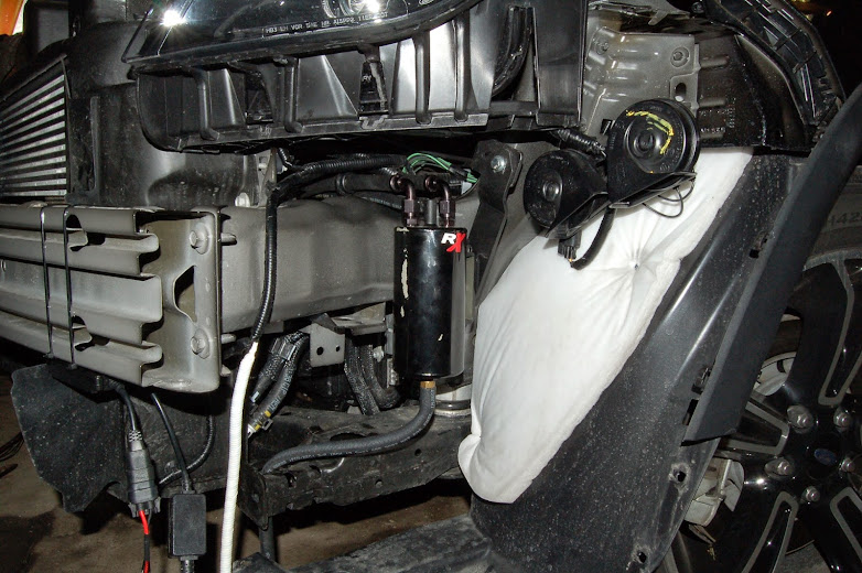
After removing the front end, I started digging around...I quickly realized my initial plan to mount it F-150 style, in front of the radiator, was simply not going to happen. Which honestly, I was fine with, since I'm not big on robbing
any air flow from the radiator or CAC. BUT THERE'S GOOD NEWS!! Although I have no idea what lies behind the SHO fenders (sorry guys) the XSport has LOADS of room in front of the wheel wells and behind the front bumper. Originally, I wanted to stay nearest the PCV as I could...and that would be the passenger's side. However, with the washer fluid reservoir occupying part of my real-estate, I started examining my driver's side options.
After removing the catch can from it's previously mounted home, I dismantled the mounting bracket, and started test-fitting my alternatives. Similarly to the top-side mounting endeavor, I found a vacant mounting tab, again with the perfect size mounting hole already drilled in it. Using only the provided mounting bracket, I was able to align the can perfectly upright, and at the correct height.
I took avid mental notes prior to moving the bumper regarding clearance and access issues from underneath. The original ford plans must have had an Rx can drawn up and removed at the last second because
yet again there was a perfect drain hose/valve option to be had. I am terribly happy with the new layout, and while you can get the gist of things from the pic below, I'll explain how it all worked out...ENJOY!

First off; while test-fitting the engine cover after the original mounting, it made a bit of a rub on the can...resulting in a bit of a peel-off-scar down the side of the can. I'll consider re-painting / powder coating later. So for now, please forgive the greasy fingerprints and franken-can.

Step 1: Prior to mounting the can in front of the wheel, remove the valve from the bottom of the can

While you have it in your hand; this is the perfect time to rebuild the valve and can. I used some teflon pipe tape...may not be necessary, but it made me feel better.
Take one of the threaded hose barbs and thread it in to the bottom of the catch can.
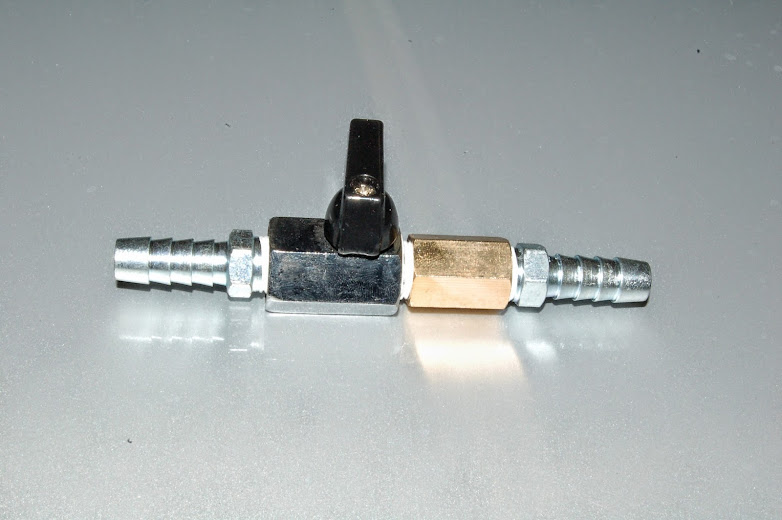
For rebuilding the valve:
Attach one of the threaded hose barbs to (what will be) the bottom of the valve .
Attach the double female connector to the top of the valve, and the last threaded hose barb to the top of it.

Tighten with a wrench:
Now you can mount your catch can. You should find an existing mounting tab with a pre-drilled hole. You can manipulate your bracket as such and mount the bracket as low on the can as possible. Use the upper two holes on the can, and slide the can as low as possible within the bracket. As you can see, you're doing this for the purpose of hose-alignment.

You will be feeding the hoses through either from can, or engine side (either way). If you look from the outside, you can see a visible channel that runs underneath the stock air box, and above the frame. You will run one line at a time underneath the airbox.

Once they have been run through the channel, they will turn upwards, and follow the intake pipes / charge pipes to the rear of the engine. If you already have the hole drilled / tapped in the front intake pipe, you can leave it as is. If you're installing for the first time, there is no need to drill the front pipe as you can attach the hose to the vacant vacuum barb on the intake pipe (shown here as "capped off"). Also, regarding the rear intake pipe: If you are installing for the first time, I recommend installing a 90* elbow in the hose, after attaching hose to the fitting that's been tapped into the rear pipe. This takes the pressure off the fitting, and makes for a cleaner install than just bending the pipe. If you're already installed (like I was), it's just as simple to cut the hose and install the elbow.
So, you now have three lines, all running together from the catch can.
Outside fitting #1 - Runs to the front intake pipe fitting or vacuum barb, and rear intake pipe fitting. This is a source of vacuum for the can.
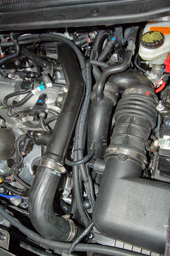
Outside fitting #2 - Runs to the vacuum barb on the Intake Manifold.
Center elbow fitting - Runs to the PCV vacuum barb located on the rear valve cover.
Both are visible in this picture. Also, I found that it gave me a much better angle off the IM vacuum barb to replace this connector with the 120* connector that was left over from the CSS install, rather than the 90* connector that was originally there. This allowed me to run my line directly back towards the PCV and zip tie them together.

As for the remote drain:
attach a length of your 3/8" hose to the bottom of the catch can.
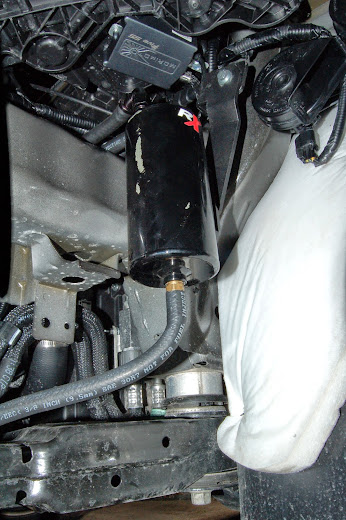
You should now be able to locate the frame extension as indicated below. Towards the front of the frame extension there is a 1/2" hole that already exists, and runs straight through to the bottom of the frame extension. You will run your hose through this hole.
Now, here is where the choice of hardware used to rebuild the valve becomes important. On the top side of the valve, you could have used a threaded female to hose barb connector, rather than the coupling like I indicated...this would have saved you some space. But, for this particular mounting, I found it to be easier to manipulate the valve when it was spaced away from the frame extension. The coupling is large enough that it does not fit through the hole, so with the addition of a zip-tie, makes for a VERY sturdy and easily accessible mounting location. I added the probably unnecessary 3/8" rubber nipple just to keep any crud out of the lower hose barb. As you can see, there's plenty of room that leaves it still quite tucked away behind the skirt.

Congratulations! You have now successfully completed the install!...or re-route!...either way congrats.
This is what you should see under your hood.

With the can now re-routed completely out of the engine bay, your engine cover should fit back on without a problem. Since all of your hoses are tucked down neatly between the charge pipe and intake pipe.
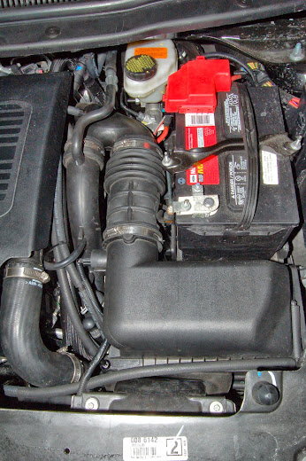
Looks almost stock if not for the CSS.


Why, other than a cleaner looking install did we do this?
Well, the main benefit is to mount it somewhere outside of the engine compartment where it will remain cooler, thus enhancing the condensation /collection effects of the can.
As usual...with any questions / comments / concerns...please don't hesitate to ask!