Catch can install:Do not order Monster option, it will not fit!
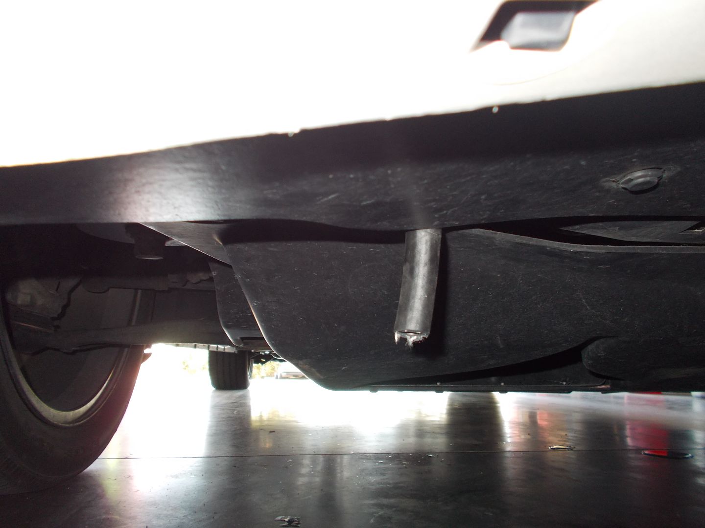
Breather option is not required on the catch can for daily driversAnd now onto the install. The Flex is only different from the F150 by the engine being a longitudinal configuration, so fitment of the can for mounting was a bit more difficult, but we found a pretty ideal spot and draining will be through a drain hose that protrudes out the bottom so it can be accessed easily during oil changes, or simply by placing a cup under it and opening the 1/4 turn ball valve drain.
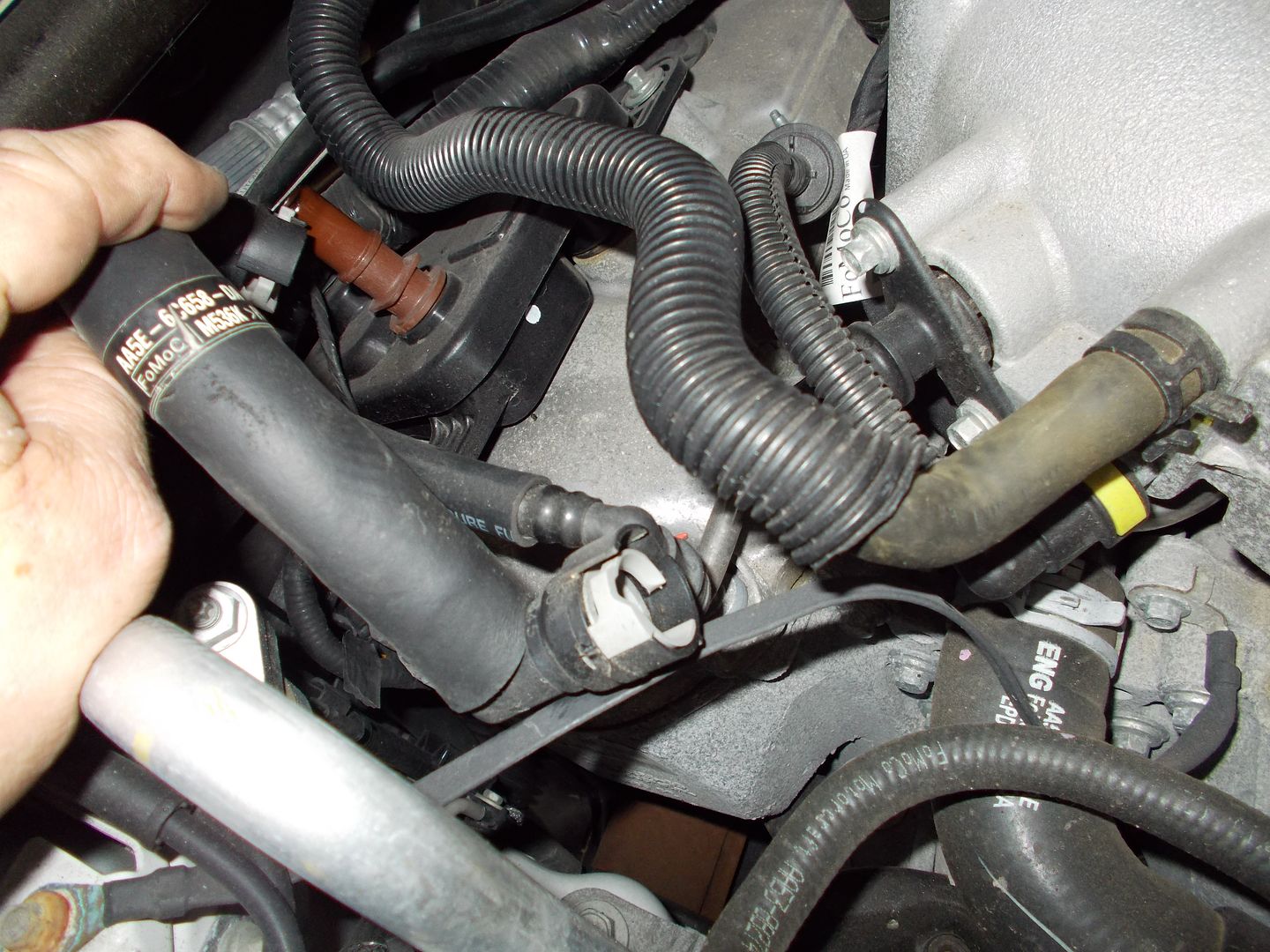
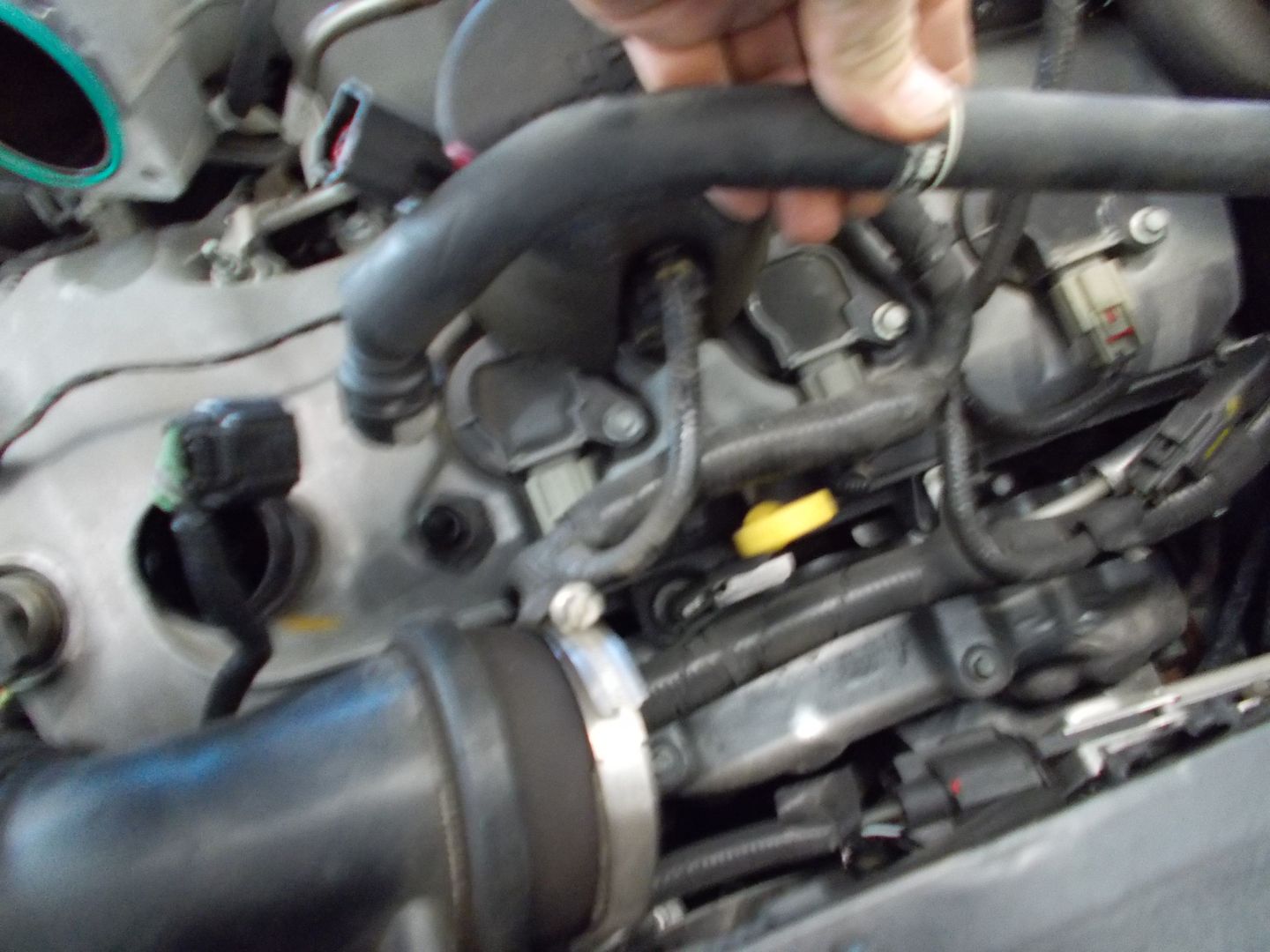
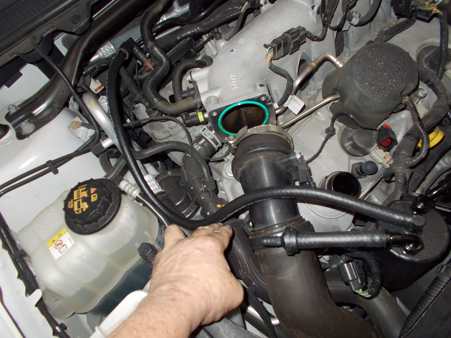
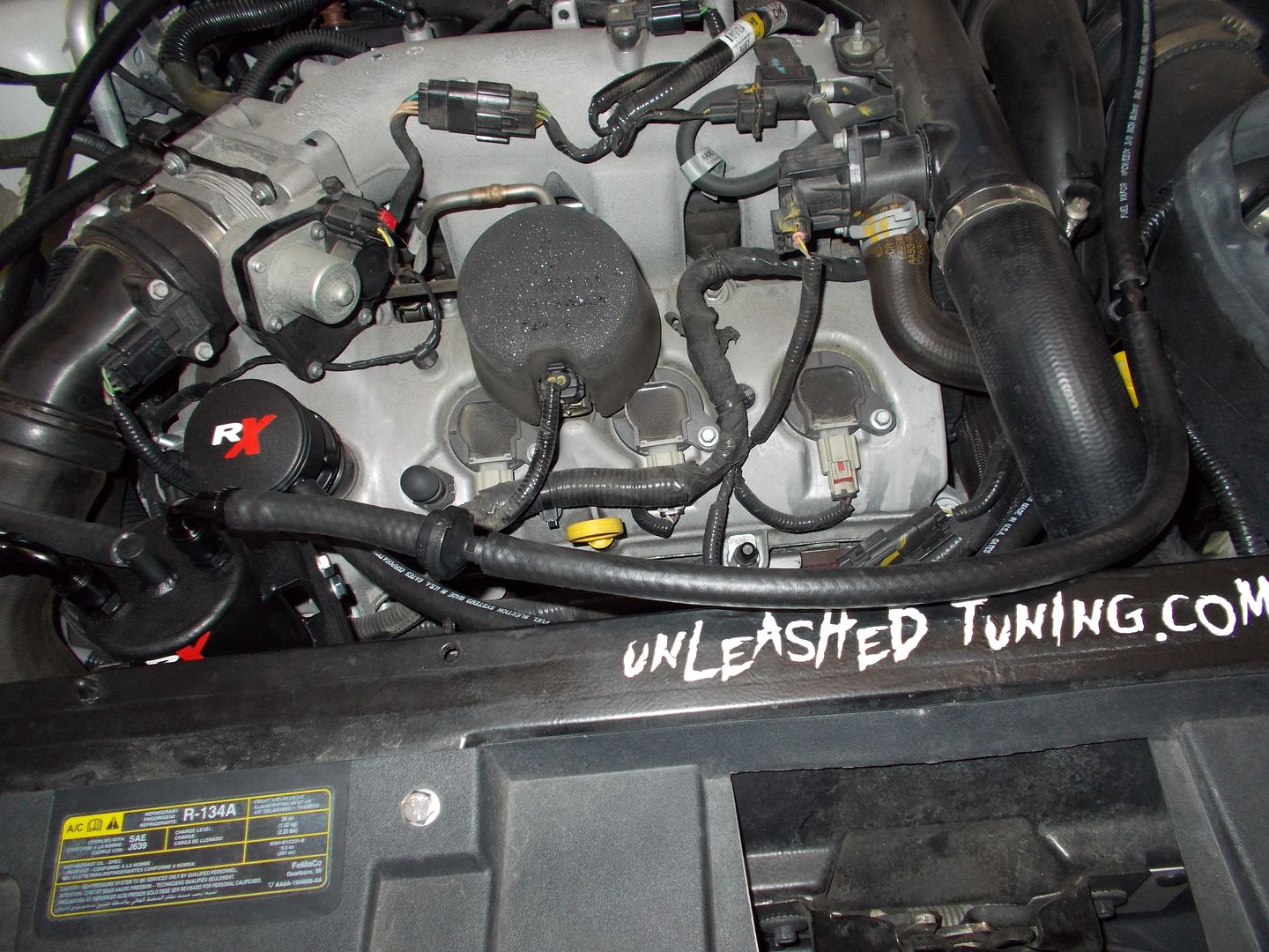
So to begin with, we remove the engine cover, and locate the tubes we will be removing.
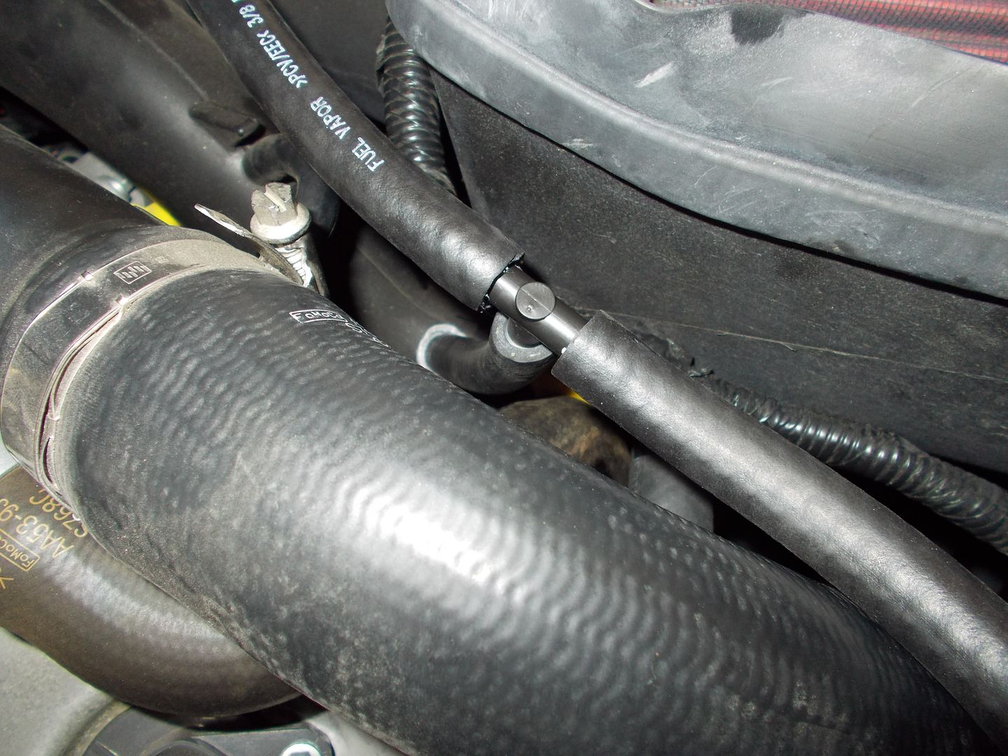
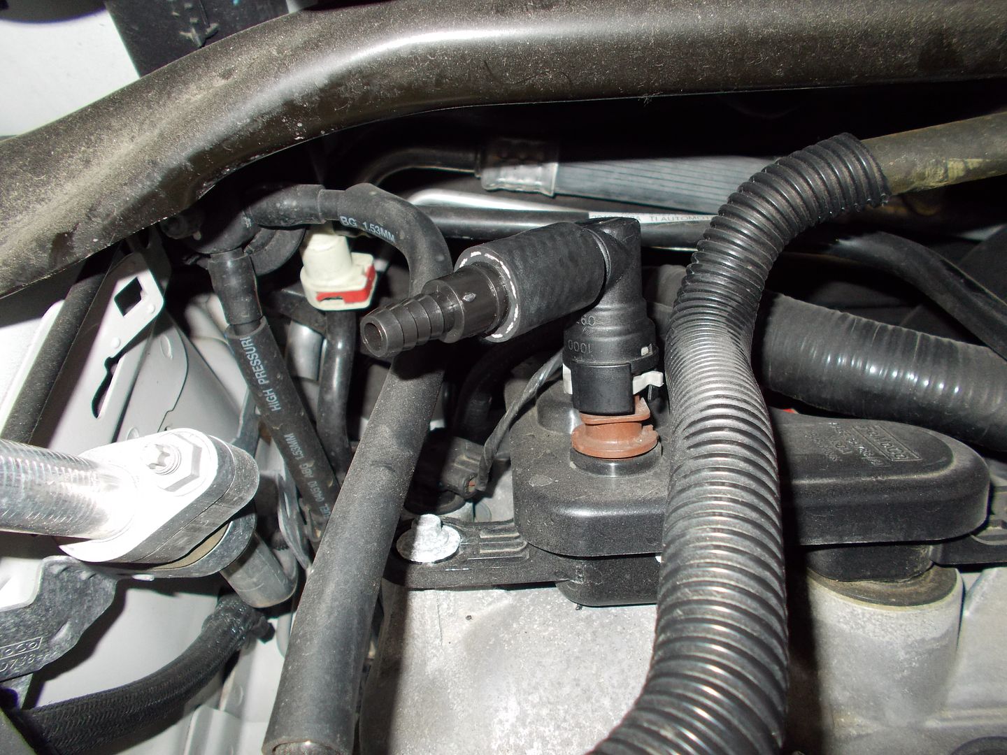
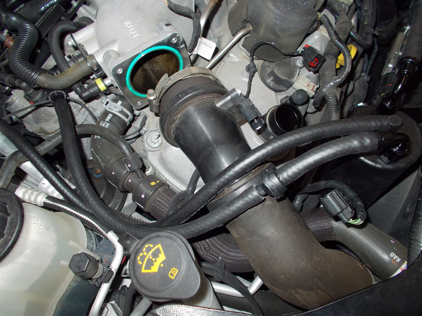
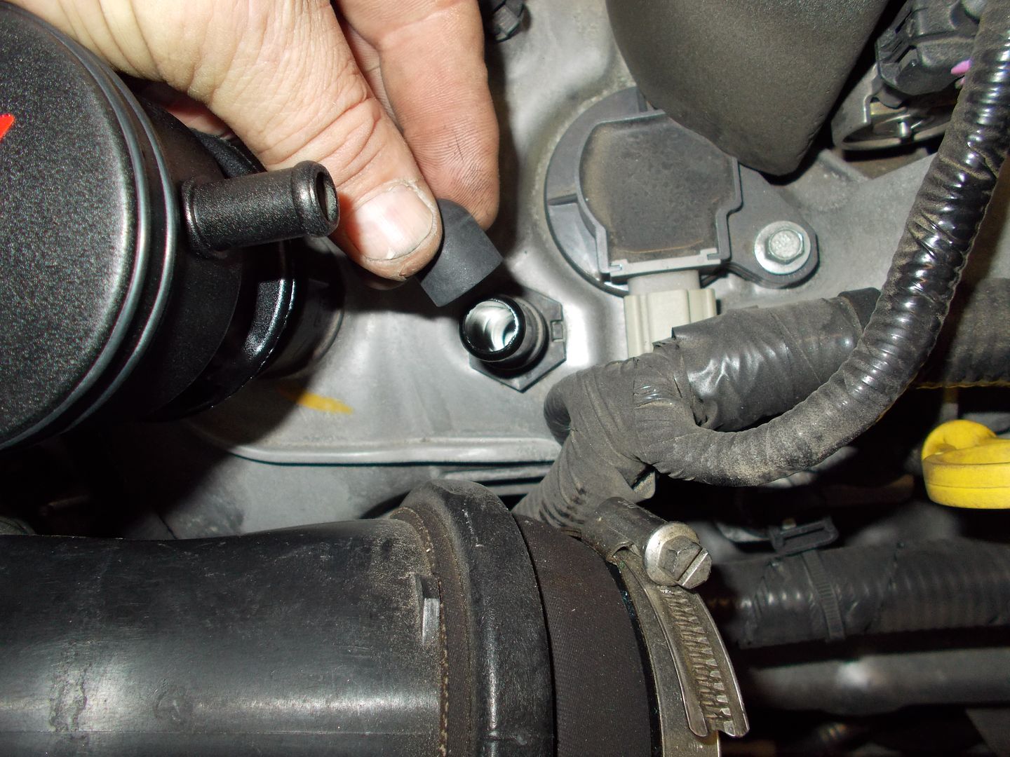
The tube from the rear most cam cover that has a integrated checkvalve from the factory runs to the barb on the intake manifold snout right behind the TB:
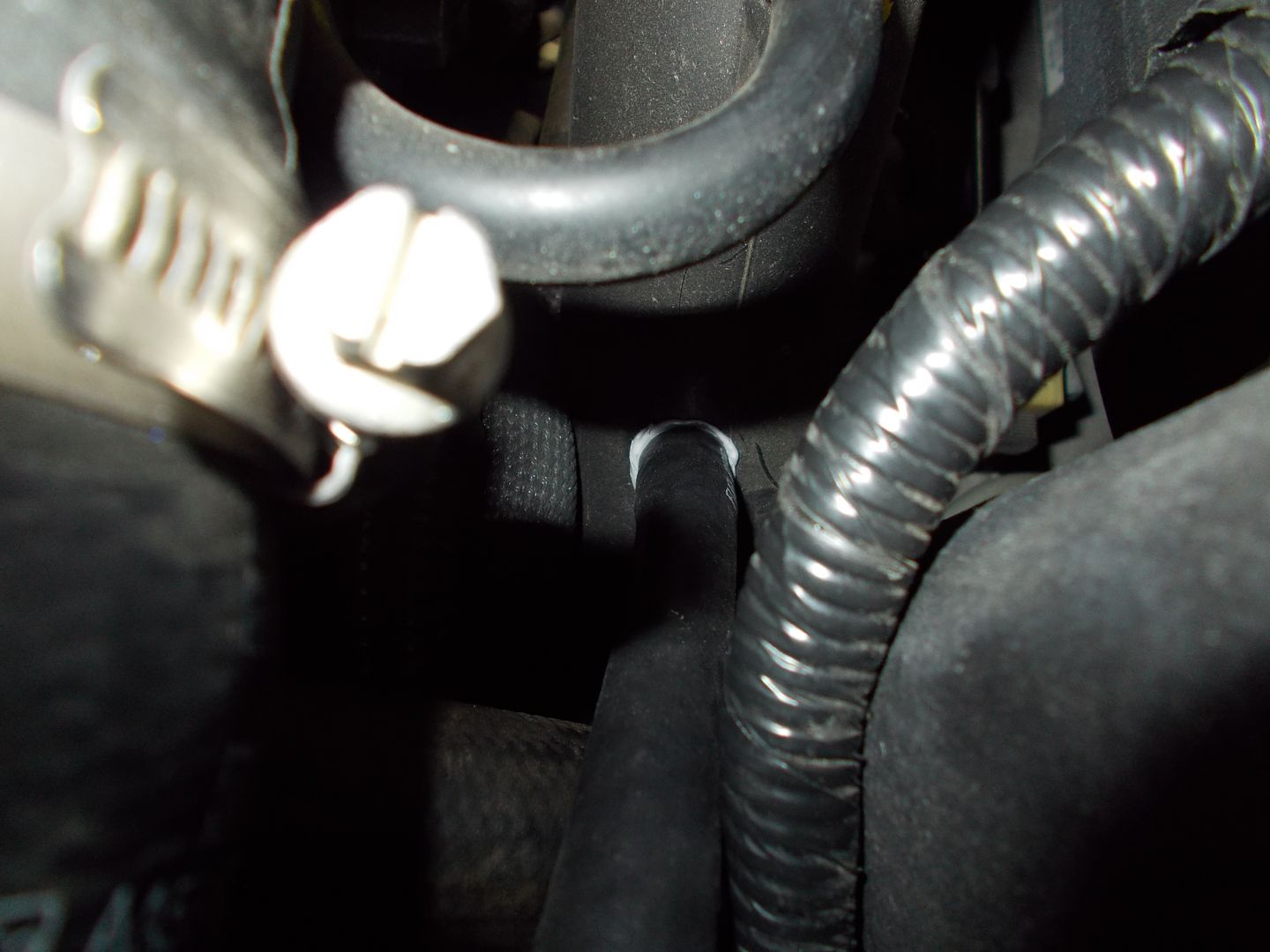
Remove the tube and using a razor blade, carefully slit the hard plastic tube at the OEM barb so it will split and allow removal:
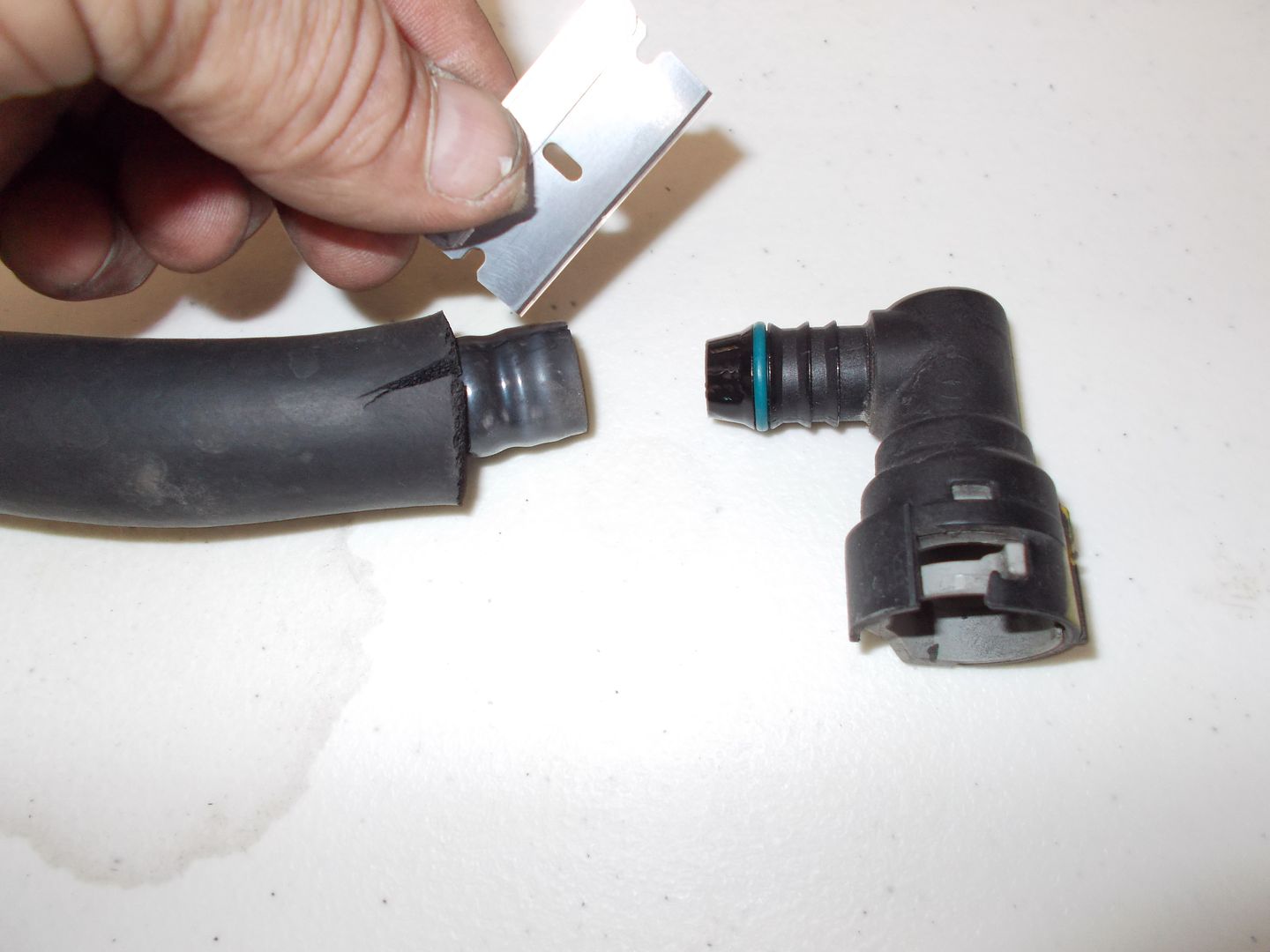
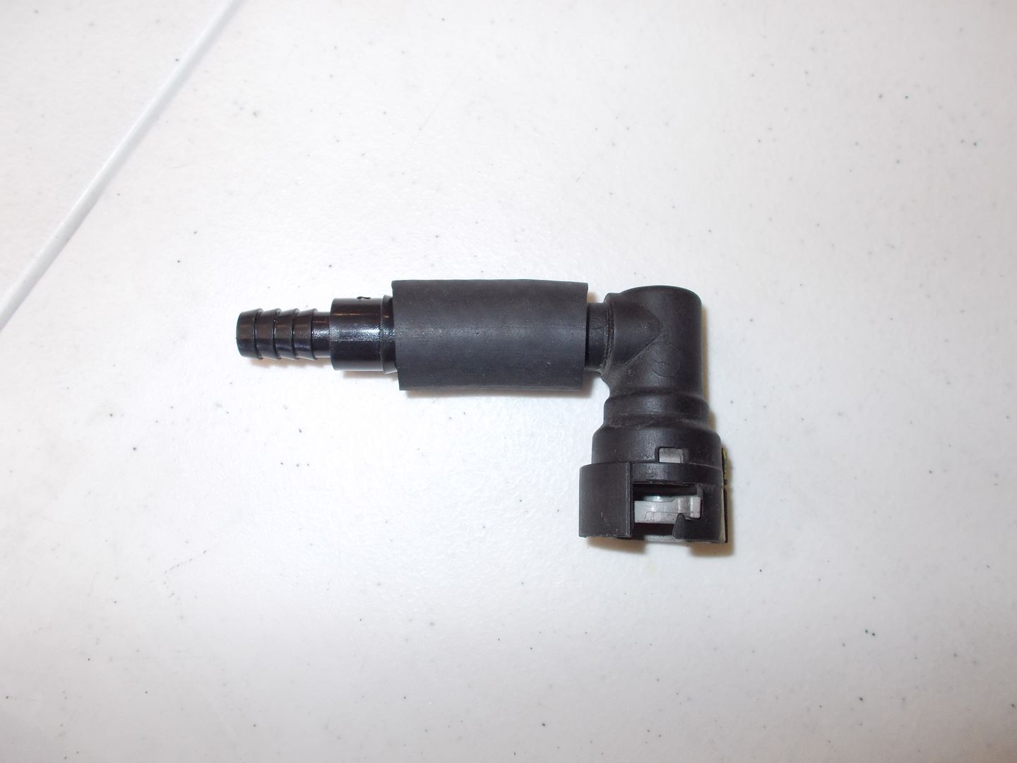
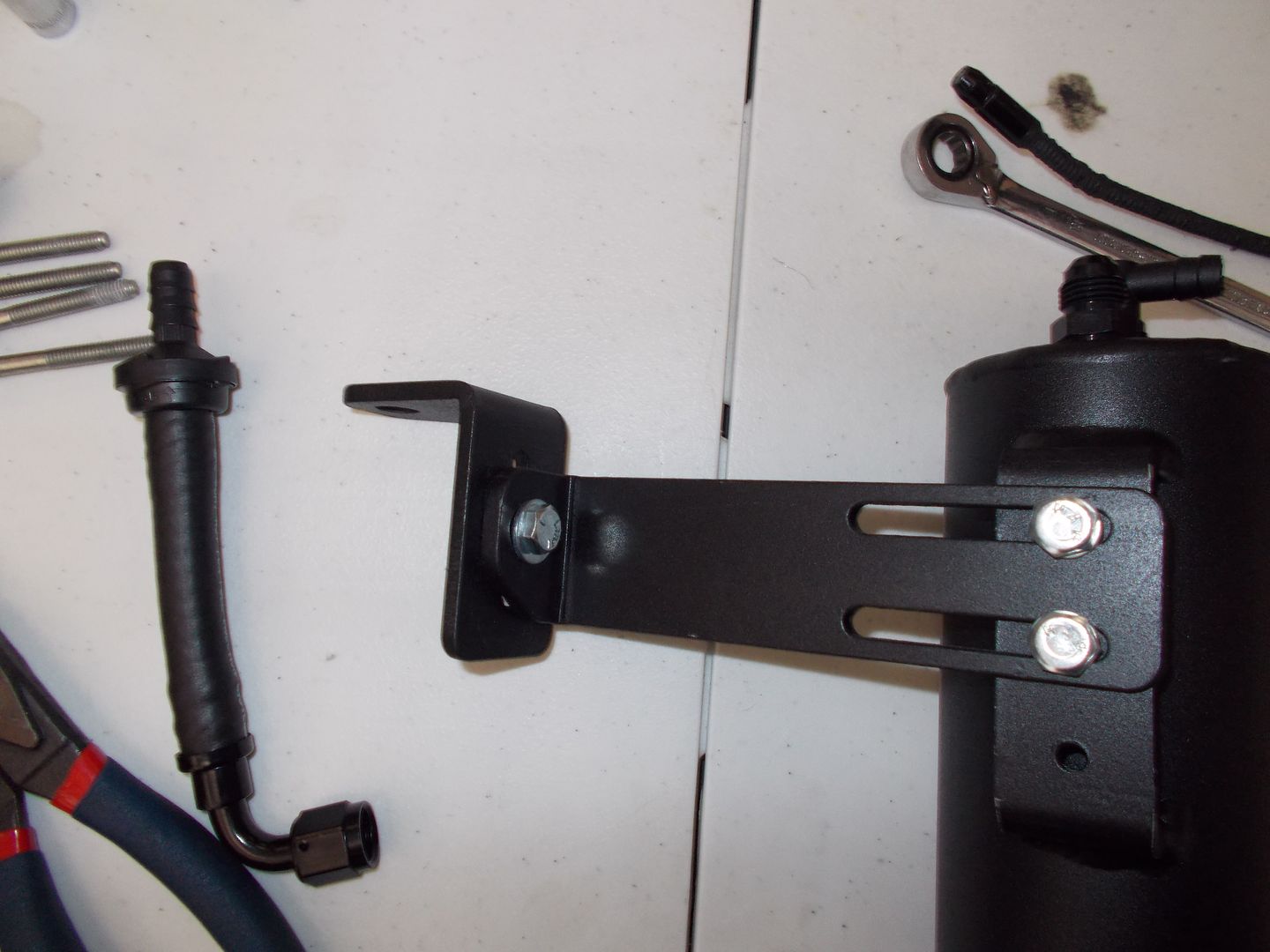
You can then use the included 5/8" short tube to attache the reducer bars to the OEM fitting so it snaps right back on:
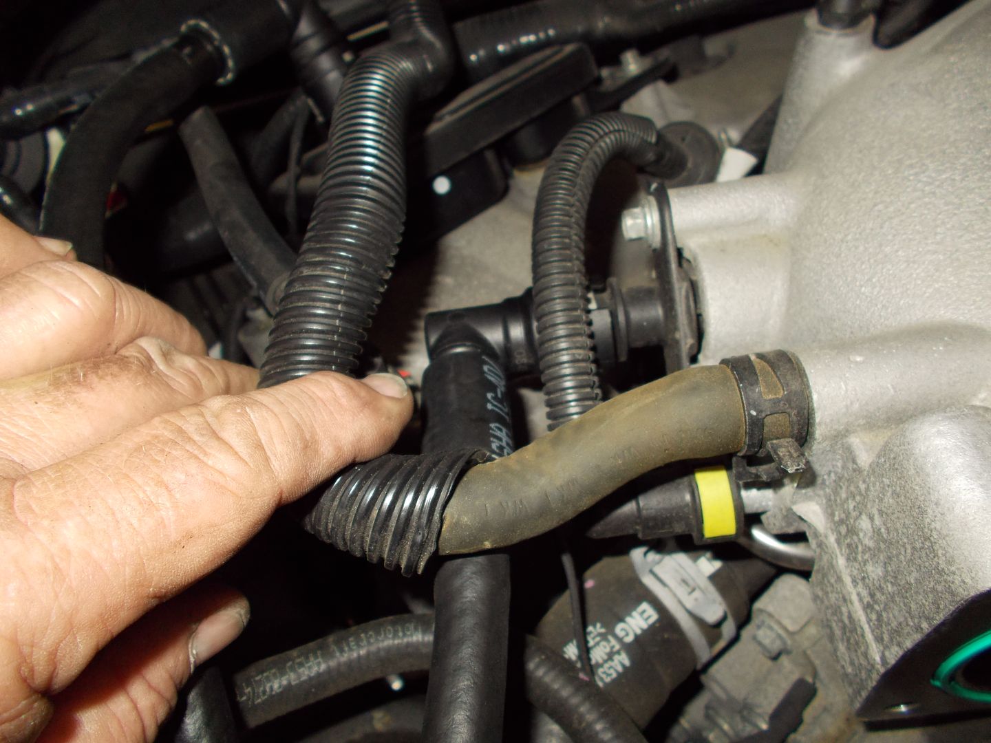
Do the same with the front cam cover cleanside line:
Now we mount the can itself. Note the bracket is 2 piece, and is adjustable. We remove the single plastic fastener shown to open an existing hole to mount to:
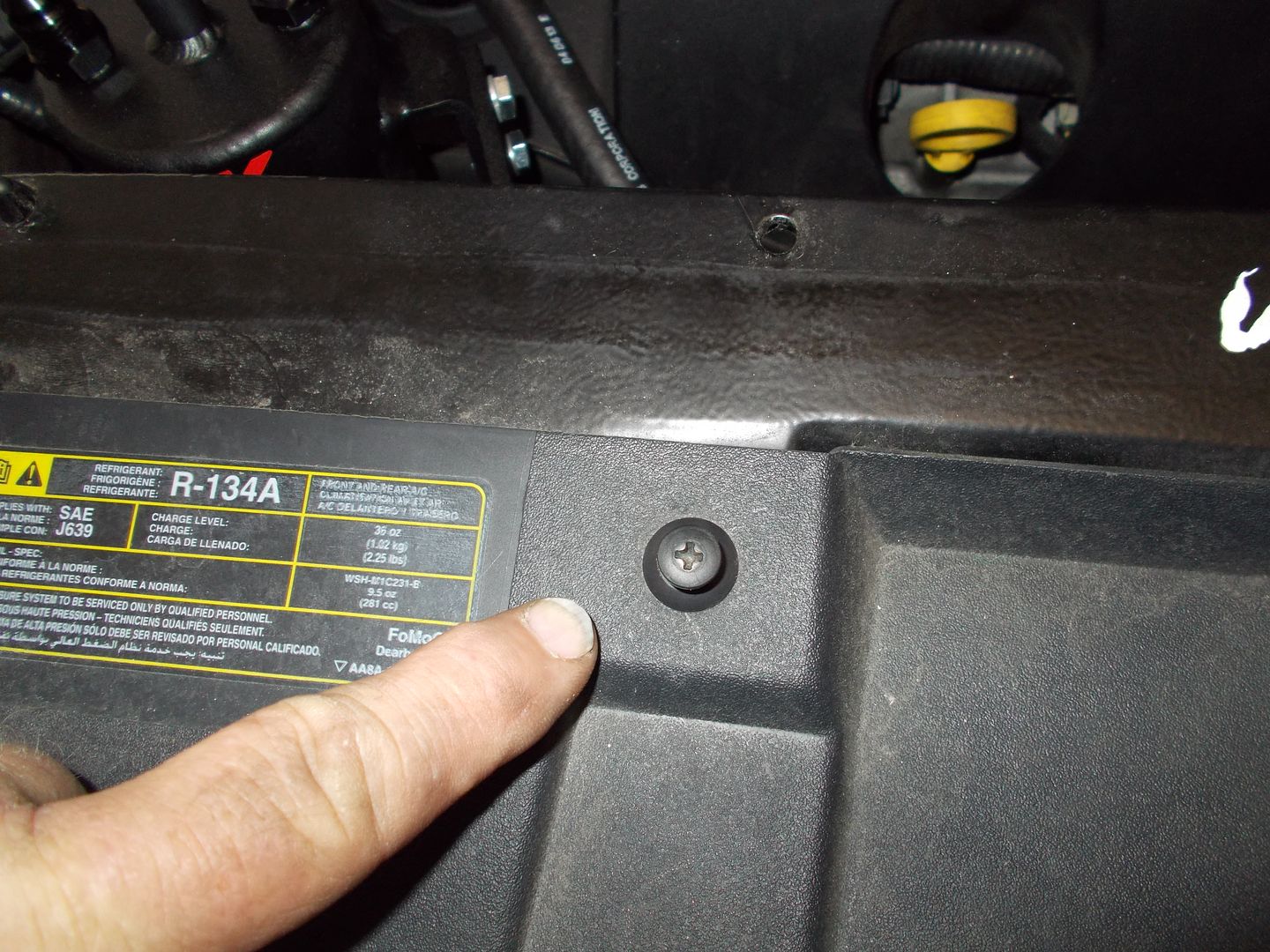
Reaching up under the cowl you can place the bracket and fasten with the 1/4 20 x 1.5" bolt and nut:
Now connect each line as follows. The line from the rear cam cover will connect to the center of the catchcan (inlet) with no checkvalve.
One outer fitting from the can, with checkvalve flowing away from the can connects to the intake manifold vacuum barb.
The final outlet from the can connects to the T'd line from each inlet tube providing suction for evacuation while in boost operation.
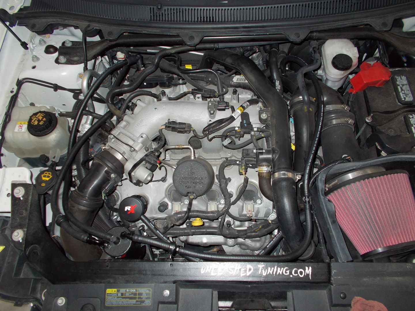
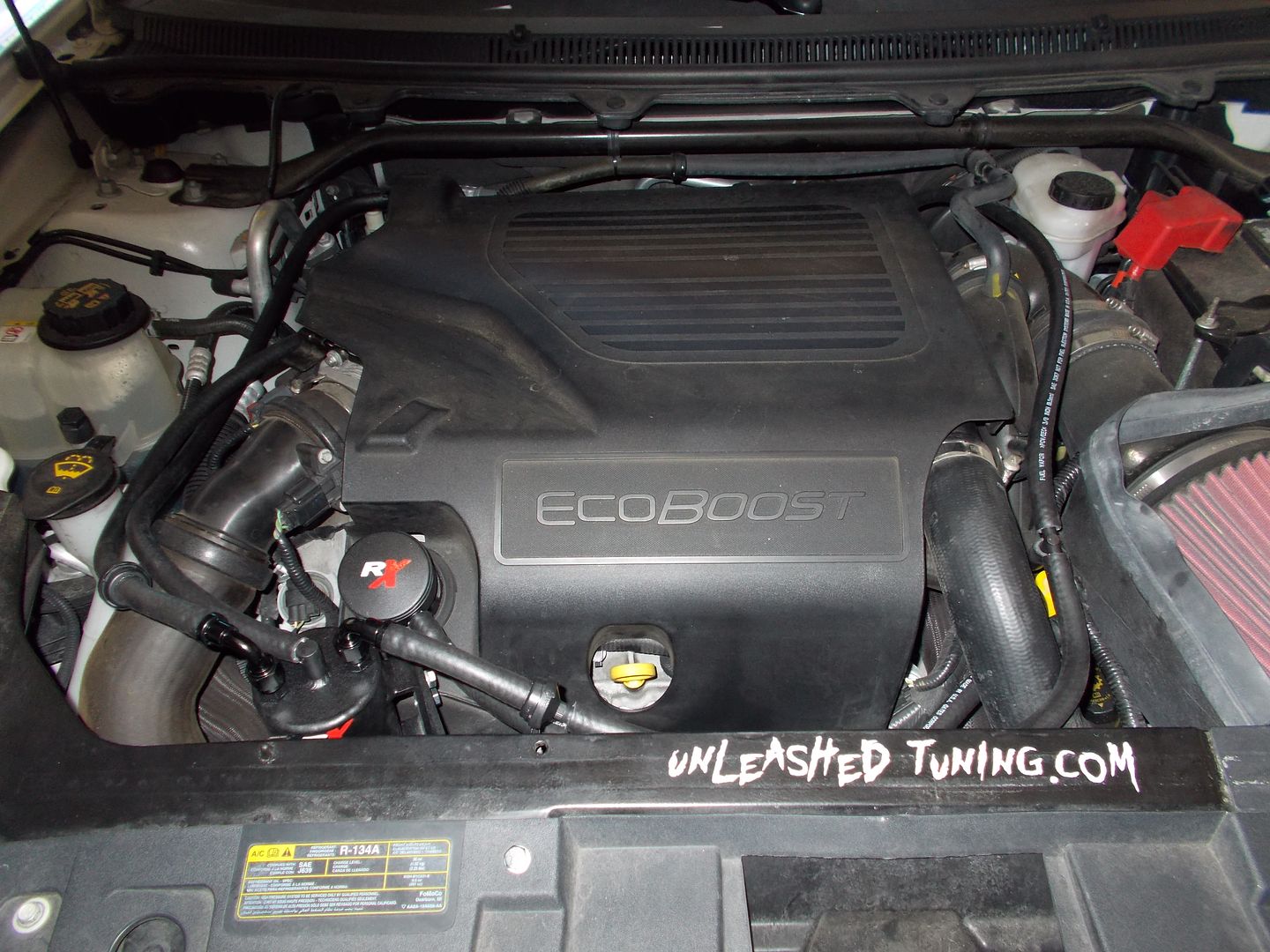
And the final finished install looks almost factory:
Clean side install:This part is a separate part use link to order - it is not included in the catch can price.The ILE style cleanside spearator will then replace the oil fill cap and use the incuded vacuum cap to cap the barb on the cam cover, running the hose from the cleanside separator to the barb on the intake pipe the OEM line originally connected to:
You have now replaced the direct line that allows oil/water/fuel to enter the charge pipes and the IC. The cleanside separator will catch and return the oil caught during the momentary reversion when transitioning from non-boost to boost.
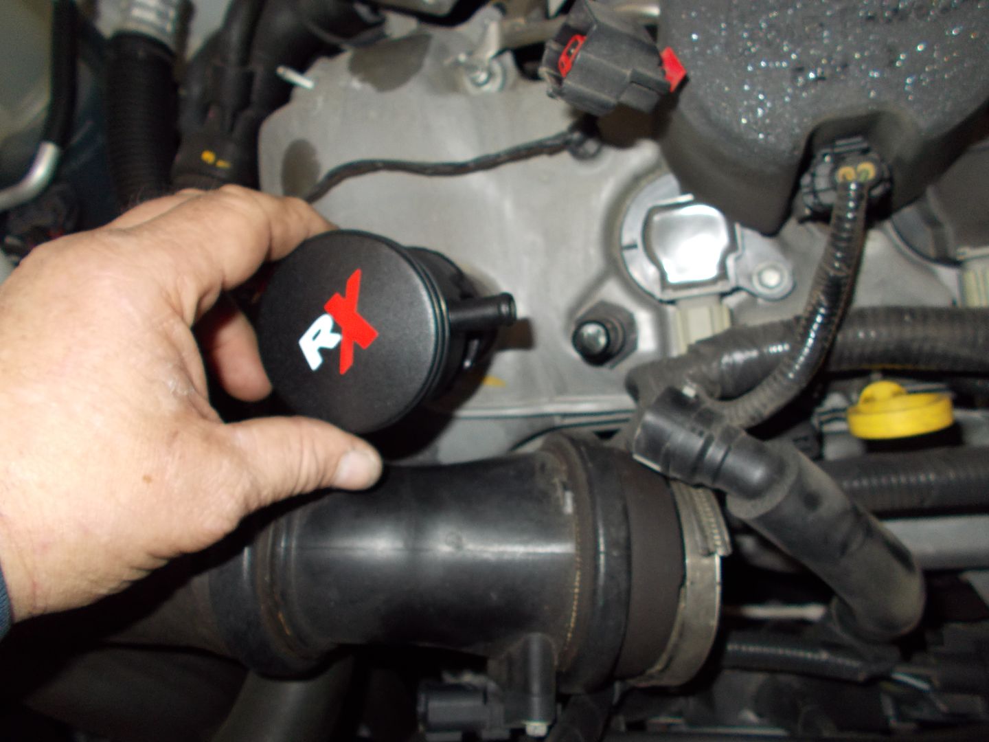
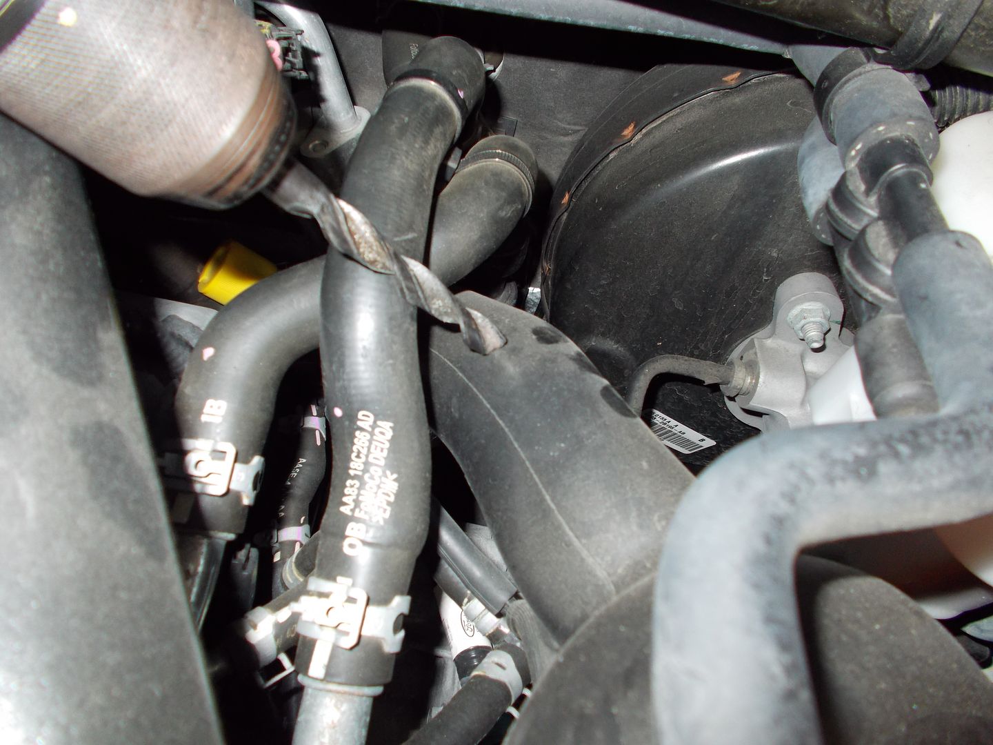
We then move to the suction source that provides evacuation during boost (note, the same source is used for the brake booster vacuum when in boost as well until later years when a aux vacuum pump is added):
We are going to drill into each inlet tube that feeds the turbos with a 3/8" drill bit (if cold temps, warm with a hair dryer). If the hole is to small to allow the barb to push in for a snug fit, ream it slightly. It also helps to add some RTV or similar sealant to the barb to ensure a good seal. Do not be concerned with any small plastic particles that may fall into the tube, these will pass harmlessly through:
The rear tube
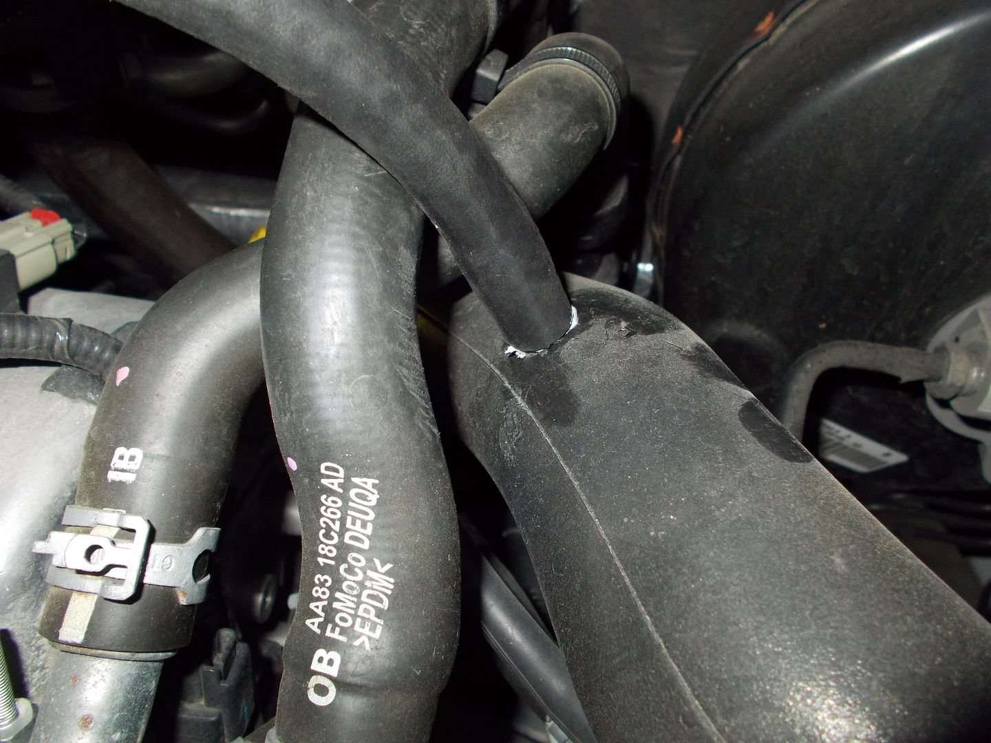
and the front tube where we T into the secondary evac outlet on the can: