• Welcome to Ecoboost Performance Forum. Please log in or sign up.
collapse

Testing Air Oil seperators

Started by ShoBoat, April 10, 2014, 10:59:52 PM

Previous topic - Next topic

ShoBoat

Quote from: JimiJak on April 14, 2014, 12:10:44 PM
I'm sure Tracy can back-track to his last post just like the rest of us. ;)

My only concern regarding the stand alone vacuum pump idea is that it would provide a static level of draw rather than being variable with the demand from the engine. Yes?

It would be static yes, however I would assume that if it's designed for a brake booster it would provide enough lift and flow for our application. We could perform a simple test to determine the lift and flow of the current setup on a RX installed on a SHO. Just to be safe. Under boost I would assume you would want lots of flow. I would be more afraid that it would be too much with the electric and start sucking oil. It may need a reducer or in some cases the 12v vacuum pump can be dialed in to provide the exact lift and flow for the correct evacuation of gases.
2012 Pearl White CTS-V Stock
2016 Fusion Titanium 2.0 EB Stock
2013 SHO Black on Black (Gone) PP, Unleashed Custom Tune, 170 TStat, SP534 Plugs, 3 Bar, Airaid Intake, PPE catted downpipes, Corsa Cat-back, H&R Springs. Focal 165KR Front Stage,2 JL W6 10 with Focal 800.1. 12.62 @ 110 mph.

Tuner Boost

Quote from: ShoBoat on April 13, 2014, 09:44:50 PM
Quote from: Tuner Boost on April 13, 2014, 03:56:43 PM
Oh, one other thing. Only the RX system corrects the PCV systems evacuation issue, adding another can  only dealing with the vapors after they have accumulated in the crankcase already and contaminated the oil.

Some of the other cans can be modified to do the same, but you will need the checkvalves, fittings, lines, etc. to accomplish this.

The RX system is complete with all needed.

To compare, you would want to use the RX single valve can for $199 if you dont want to correct the PCV system flaw.


Hey Turner Boost,
What I am trying to achieve through this simple experiment  is determining how much if any oil is being ingested through the intake tube (clean side) vs the PCV side, and 2 are the Moroso really that bad. (These are on loan from a friend) I know that the RX is superior in terms of the catch rate, and correcting flow (for your dual catch can).

Your experiment is a good one, but due to the PCV system only evacuating at idle and low throttle (at cruise there is boost present so no evacuation) so as is, the PCV system app. 80% of the time is building crankcase pressure to the point that it is forcing vapors out backwards through the cleanside, when a proper system always retains flow of "fresh in one bank, foul oil laden out the opposite". So that must be corrected or no catchcan can really do much but trap some after the fact. The cleanside should rarely have flow reversion so the foul side will be the one that should catch 95% of the oil mix.  But as the PCV system is OEM, most will be on the fresh side.  Yes, the Moroso and the 30 some others are not much better than a $15 air compressor separator. Easy to test and see. What you have done for the F150 is simply amazing from what I have seen and read. That said this thread seems to be predominantly about transverse mounted EBs, which as you know presents a different set of challenges in terms of mounting compared to the F150. I am eagerly awaiting the responses from those members with the RX mounted in their SHOs. I may or may not end up with a catch can in my own car, I can tell you this. If I do it will probably be the RX. I will take your advice and mount a simple compressor separator after the Moroso's and see what we get there. The Moroso is not that much cheaper in terms of cost. You need 2 cans and that is about $300.00. The RX is only $100 more, with the clean side separator. For a mod you will do once, I don't believe that cost is an issue.     

The transverse applications the only thing I can see different is the size and efficiency of the CAC, but that in it'self should not make as drastic of a difference in the two....so there is still some mystery that until I have steady access to a few to test different functions, I can't answer exactly why. But I sure will figure out why.

You will have to forgive my ignorance, the defect in the PCV system. Is this not present in all boosted cars? Like the CTS-V or ZR1? I am not familiar in how GM routes the PCV on their boosted cars. But from the CTS-V vid I would assume this would be the case.

One would think so, but there are several types of forced induction. The Caddy CTSv, Vette ZR1, camaro ZL1 Mustand GT500 and cobra, are all a positive displacement top mount blower that replaces the intake manifold. These do not pressurize the intake manifold as they are delivering the boost directly to the intake ports and the intercooler is water to air and mounted under the supercharger between it and the cylinder heads.  These provide vacuum at all times as it comes from the inlet side of the supercharger so it always supplies vacuum/suction, but the least at idle and low rpms, and the most at high RPM's SO there is no pressure/boost issues as far as evacuation like a turbo or a centrifugal supercharger that pressurizes the air charge before it travels through the intercooler and then pressurizes the intake manifold. That is why the issues unique to those types of FI.

A few questions, if efficient evacuation and constant is what we are looking for what about connecting a simple vacuum pump to the 2nd port on the RX? This would eliminate the need to drill into the intake tubing and would ensure a constant rate of evacuation, I understand that this would bypass routing the PVC gases back to the intake. However this would only happen under boost and would completely eliminate any chance of crud getting into the CAC. The RX would not be reliant on vacuum that may or may not be present in the intake tube. And with the RX before it there would be minimal chance of fouling the pump. It sounds complicated but with all the different configurations on the EB intake tubing depending on the car or truck, this would ensure that the system is performing at peak efficiency regardless of the application.

Absolutely correct. The issue is, we have not been able to, nor has anyone developed one that can do what needs. That is maintain enough vacuum and CFM of flow, and not be damaged by the mix of oil/gasoline/sulfuric acid, etc. All to date only last a short time before failure (we have been trying different solutions for the past 10 plus years) and a belt driven unit like we use on our race applications that will maintain the correct amount of vacuum and flow will not last on the street.  We do use the GM small unit for a big cam build where there is not enough vacuum for a brake booster and add them with great success, but they will fail in no time if used for crankcase evac, and only provide a fraction of the volume needed to work.
In mounting the RX, it seems that the only 2 locations that we are able to mount the unit (on the SHO) are above the exhaust manifold and behind the coolant reservoir. In comparison to the F150 which is mounted in front of the rad which is the coolest spot to put it. There is space to mount the RX there on the SHO, Flex and Explorer. However reaching the drain valve would be a real pain, is it possible to either hard plumb the tubing to a valve lower down. This way you could simply reach under the front bumper and turn the valve there. Or a have a remote release for valve attached to a cable release for example? This would really free up where the can could be mounted, and then mounted somewhere cooler to maximize the condensing effect.         
Yes, excellent ideas and we are working on a remote drain. Currently we can have the option for any that want with the 1/4 turn drain valve that is located under the car near the oil drain, but a remote cable operated would be great.


Good job Jimijak.....you have most of it correct. I hope I answered all the rest of the questions above. This is a great thread (thanks shoboat and others!) as this is probably the most misunderstood system on todays cars. In the "old days" all were the same basically domestic and import.

krdiesel

Why does the EB only evacuate only under low and no boost?    The 6.0 intake for the CCV is right before the turbo. So you always have vac on the CCV system.  That way you have more vac under heavy boost when it is needed/


BiGMaC

Quote from: krdiesel on April 14, 2014, 02:22:06 PM
Why does the EB only evacuate only under low and no boost?    The 6.0 intake for the CCV is right before the turbo. So you always have vac on the CCV system.  That way you have more vac under heavy boost when it is needed/

To prevent liquid ingestion into the CAC from increased vacuum at higher boost creating more vacuum on the RX catch can.

•2013 Taurus SHO nonPP - All Ford factory options, 3BAR MAP, LMS v8 tune (mods for 3BAR, DPs, and T-stat), Paint & plastic correction, CQuart finest all exterior surfaces, limo black window tint,VLED Triton switchbacks, Daytime BrightLites switchback DRLs, full interior and exterior LED conversion, Lamin-X charcoal blackout tail lights and reflectors, PPE catted and coated downpipes, EBPP coated hotpipes with BoVs VTA, MDesign CAI
•2013 F250 CC Lariat 6.7EB Diesel -stock

krdiesel

Just thinking "out side"  have a hose from air filter to valve cover, then from other valve cover to rx catch can, then to right in front of turbo.


dalum

Per the emissions standards this all has to be self contained so any gasses coming out will get ingested back into the system.  The "best" thing would be the off road replacement for the oil cap that is just an air filter.  It lets in fresh air and any oil that would be blown back out during reversal hits the inside of the filter and doesn't go anywhere near the intercooler.

It's my understanding our pcv system fails under boost because there is pressure instead of vacuum at the inlet in the throttle body.  The inlet into the "intake" port on the valve cover is also too close to the turbo so lower pressure in this region create a small vacuum on this line as well.  This vacuum is normally equaled out by the vacuum at the throttle body port so the positive nature of the exhaust port would keep stuff flowing in the right direction under non-boost.

The 2 lines added in front of each turbo serve as the highest vacuum source for the pcv system (through the can) while in boost.  The clean side separator's intake (as well as the clean sides intake from the factory) should be to open atmosphere but since thats illegal its placed as close to the main intake filter as possible so it will have as little vacuum on this line as possible.
2013 Non-PP SHO

dalum

What I think would work is a check valved T on the clean side intake.  When there is no pressure in the line it would pull fresh air in from its own standalone filter.  When the engine flips to boost the line would get pressurized changing the check valve to a line in the intake system.  That should give a zero vacuum source for fresh air and still plumb gasses back into the system when required.
2013 Non-PP SHO

Tuner Boost

krdiesel.  Proper evacuation must maintain a constant flow of fresh air in one bank, and foul air out the other as this basic training video describes. This is a good video on the basics:
https://www.youtube.com/watch?v=EPIfI9aZHt4

The clean side fresh air comes from the one side turbo inlet pipe, but really should come from just after the air filter so it does not overcome the "flushing" or "purging" flow direction of the PCV system.  So on the Flex and the other longitudinal oriented engines the cleanside should be tapped into the air box, or the main intake tube just after the air filter so there is little suction, and still filtered fresh air. Then the opposite bank (pass side in truck, rear side in cars) is where these oil/fuel/water/sulfuric acid laden vapors are evacuated.  If you allow the turbo inlet to switch the flow direction, this allows these gasses to accumulate and collect in the crankcase causing contamination to the engine oil. So the OEM system works fine at idle and low throttle when zero boost is present, maintaining a constant evacuation of these compounds not allowing them the chance to accumulate in the crankcase. But as soon as the engine begins to make boost, which is quite rapid due to the design of the turbo system and the small size of them, the checkvalve in the pass side valve cover (rear on transverse) closes and then there is NO evacuation taking place.  Then blow by produces crankcase pressure that eventually builds to the point that it pushes "out the in" and it is during this time that these compounds accumulate and condense. Then as the pressure is pushing out the inlet, some of this concentrated mix is also drawn with it and sucked into the turbo on that side, and pushed into the CAC where some of it condenses and accumulates there. Since this is backwards of the intended flow path/direction, and there is no opening of an alternative fresh air source from the other bank, most of the mix accumulates in a concentration that causes what you see drained from the cans on the trucks. So, this is similar to a smoke filled room. Open one window, and only a small amount of smoke will escape. Open one on the opposite end of the room and have a fan attached, and the room clears in no time.  The easiest way to correct this flaw and retain emissions compliancy, is to simply add an alternate suction source so that there is a nearly seamless switch of evacuation suction source, and the correct direction of flow, and the constant evacuation of the damaging compounds, remains constant so these are removed at a pretty steady rate, and a small amount steadily than a gulp of concentrate.


Quote from: dalum on April 14, 2014, 03:25:33 PM
Per the emissions standards this all has to be self contained so any gasses coming out will get ingested back into the system.  The "best" thing would be the off road replacement for the oil cap that is just an air filter.  It lets in fresh air and any oil that would be blown back out during reversal hits the inside of the filter and doesn't go anywhere near the intercooler.

It's my understanding our pcv system fails under boost because there is pressure instead of vacuum at the inlet in the throttle body.  The inlet into the "intake" port on the valve cover is also too close to the turbo so lower pressure in this region create a small vacuum on this line as well.  This vacuum is normally equaled out by the vacuum at the throttle body port so the positive nature of the exhaust port would keep stuff flowing in the right direction under non-boost.

The 2 lines added in front of each turbo serve as the highest vacuum source for the pcv system (through the can) while in boost.  The clean side separator's intake (as well as the clean sides intake from the factory) should be to open atmosphere but since thats illegal its placed as close to the main intake filter as possible so it will have as little vacuum on this line as possible.

Excellent understanding!!  But the next post would not work correctly. We always want a flow of fresh in one side, foul out the other, but an excellent idea.  This is good thinking and understanding all.

The ideal system is a belt driven vacuum pump like we run on all of our alky drag engines.


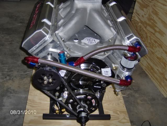
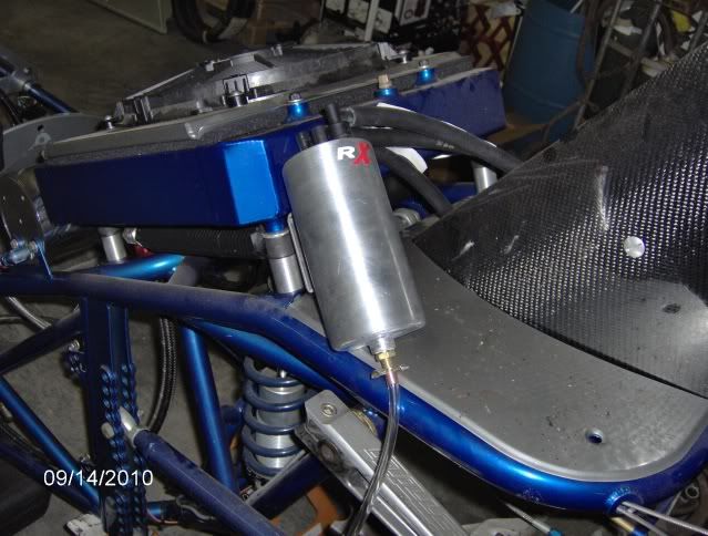
We have the vacuum pump maintain a steady 14-15" of vacuum at all times on the crankcase, this removes ALL water, unburnt fuel, etc. from the crankcase constantly and also reduces the amount of energy required for the pistons to move downward in the bore (why most with the RX system claim more power, etc.) as well as prevent ring "flutter" from pressure (we always want the rings steady and sealing as best they can against the cylinder wall). We have an adjustable vacuum relief valve on the opposite valve cover as we pull from so we maintain the flow direction. The picture above shows the vac relief valve plumbed into the system near the pump. It will maintain vac level, but will not allow cross flow so we changed it's location before installation of the engine in that dragster.

panther427

I wonder if there defective PCV was really the cause of the F150 issues with stalling and stuff... they would get too much flow into the CAC and once it hit the CAC the vapor would condense into water.. Then going Full throttle would pull a gulp of condensed liquid into the motor...
2013 SHO

JimiJak

It's been a long day...but why not put a check valve on the clean side line??

Also, I'm confused; I know the system must be self-containable, but why are we trying to supply positive pressure into the crankcase with a line connected to an area with vacuum?
"America is all about speed. Hot, nasty, badass speed." - Eleanor Roosevelt

2014 XSport Black Betty Build

FoMoCoSHO

Quote from: krdiesel on April 14, 2014, 02:22:06 PM
Why does the EB only evacuate only under low and no boost?    The 6.0 intake for the CCV is right before the turbo. So you always have vac on the CCV system.  That way you have more vac under heavy boost when it is needed/
According to Ford, that info is inaccurate.

It does evacuate under boost and routs the vapors through the crankcase into the LH turbo inlet.

JimiJak

Quote from: FoMoCoSHO on April 14, 2014, 10:46:12 PM
Quote from: krdiesel on April 14, 2014, 02:22:06 PM
Why does the EB only evacuate only under low and no boost?    The 6.0 intake for the CCV is right before the turbo. So you always have vac on the CCV system.  That way you have more vac under heavy boost when it is needed/
According to Ford, that info is inaccurate.

It does evacuate under boost and routs the vapors through the crankcase into the LH turbo inlet.

The LH turbo inlet (which in our txverse mount should be the rear side)?? The PCV line doesn't go anywhere near the rear turbo. OEM setup; it goes directly into the IM.
The clean side is plumed into the front side intake pipe, just before the turbo...but that would only evac if the system were flowing backwards...
Regardless, even if it was plumbed into the rear turbo inlet, that would mean its next stop post-turbo would be the CAC...and that's bad.
Where did you read that??
"America is all about speed. Hot, nasty, badass speed." - Eleanor Roosevelt

2014 XSport Black Betty Build

FoMoCoSHO

Quote from: JimiJak on April 14, 2014, 10:52:40 PM
Quote from: FoMoCoSHO on April 14, 2014, 10:46:12 PM
Quote from: krdiesel on April 14, 2014, 02:22:06 PM
Why does the EB only evacuate only under low and no boost?    The 6.0 intake for the CCV is right before the turbo. So you always have vac on the CCV system.  That way you have more vac under heavy boost when it is needed/
According to Ford, that info is inaccurate.

It does evacuate under boost and routs the vapors through the crankcase into the LH turbo inlet.

The LH turbo inlet (which in our txverse mount should be the rear side)?? The PCV line doesn't go anywhere near the rear turbo. OEM setup; it goes directly into the IM.
The clean side is plumed into the front side intake pipe, just before the turbo...but that would only evac if the system were flowing backwards...
Regardless, even if it was plumbed into the rear turbo inlet, that would mean its next stop post-turbo would be the CAC...and that's bad.
Where did you read that??
Routed through the crankcase

JimiJak

Quote from: FoMoCoSHO on April 14, 2014, 10:54:38 PM
Quote from: JimiJak on April 14, 2014, 10:52:40 PM
Quote from: FoMoCoSHO on April 14, 2014, 10:46:12 PM
Quote from: krdiesel on April 14, 2014, 02:22:06 PM
Why does the EB only evacuate only under low and no boost?    The 6.0 intake for the CCV is right before the turbo. So you always have vac on the CCV system.  That way you have more vac under heavy boost when it is needed/
According to Ford, that info is inaccurate.

It does evacuate under boost and routs the vapors through the crankcase into the LH turbo inlet.

The LH turbo inlet (which in our txverse mount should be the rear side)?? The PCV line doesn't go anywhere near the rear turbo. OEM setup; it goes directly into the IM.
The clean side is plumed into the front side intake pipe, just before the turbo...but that would only evac if the system were flowing backwards...
Regardless, even if it was plumbed into the rear turbo inlet, that would mean its next stop post-turbo would be the CAC...and that's bad.
Where did you read that??
Routed through the crankcase

Ok...I must be missing something.
What does that mean? I mean...I get what that should mean...but how would the vapors be routed through the crankcase into a turbo??
"America is all about speed. Hot, nasty, badass speed." - Eleanor Roosevelt

2014 XSport Black Betty Build

FoMoCoSHO

Quote from: FoMoCoSHO on April 14, 2014, 10:54:38 PM
Quote from: JimiJak on April 14, 2014, 10:52:40 PM
Quote from: FoMoCoSHO on April 14, 2014, 10:46:12 PM
Quote from: krdiesel on April 14, 2014, 02:22:06 PM
Why does the EB only evacuate only under low and no boost?    The 6.0 intake for the CCV is right before the turbo. So you always have vac on the CCV system.  That way you have more vac under heavy boost when it is needed/
According to Ford, that info is inaccurate.

It does evacuate under boost and routs the vapors through the crankcase into the LH turbo inlet.

The LH turbo inlet (which in our txverse mount should be the rear side)?? The PCV line doesn't go anywhere near the rear turbo. OEM setup; it goes directly into the IM.
The clean side is plumed into the front side intake pipe, just before the turbo...but that would only evac if the system were flowing backwards...
Regardless, even if it was plumbed into the rear turbo inlet, that would mean its next stop post-turbo would be the CAC...and that's bad.
Where did you read that??


let me rephrase this...under boost the PCV check valve shuts and crankcase vapor is routed through the fresh air tube into the LH turbo inlet.