Quote from: BiGMaC on April 13, 2014, 11:02:42 PM
...the connections to the RX can, except the center top (exit)...
I think that's backwards...the center port that cannot be moved should be the access into the can, not egress. The two check valves that are installed on the other two ports identify the flow traveling away from the can; so those should be outlets x2 and the center is the inlet.
**please correct me if I'm wrong
Quote from: ShoBoat on April 13, 2014, 09:59:22 PM
I have been told that I think too much LOL, I am just trying to ensure that what I do is the best that I can and I am usually not satisfied with that will just have to do. Which is why I like to share ideas on here, hell if it makes it better for all of us then BONUS!
ShoBoat;
I think you and I are very similar in that regard.
I spent about 25 minutes staring into my engine bay this afternoon, pondering this very issue. ...plus who knows how long writing this post. LOL Oh well, that's what down time on the ambulance is for! (EMS - Earn Money Sleeping ...or in this case typing)
First, if it's ok; I would like to establish my interpretation of how the EB TxVerse PCV system works, so it can be broken down and examined by us all (and to make sure I'm understanding everything correctly).
NOTE: If you want to skip the breakdown, go to the end of the green type.
- The inlet port of the Rx can is located in the center, and fed from the PCV valve on the rear valve cover.
- PCV stands for Positive Crankcase Ventilation, which tells me the gasses passing through this PCV-valve are being pushed out by pressure, rather than pulled by vacuum.
- PCV by definition, dictates that air pressure inside the crankcase is slightly higher than 1bar (1bar = standing atmospheric pressure).
- As the intake air flows ---> through the TB, ---> past the IM vacuum barb, ---> and through the IM itself, a venturi effect is caused on the IM vacuum barb, resulting in a pulling effect on the gasses that were being pushed out of the PCV valve. They are now being pulled into the IM.
- This is what tells the system which direction to flow, since the positive pressure inside the crankcase would otherwise try to escape in all directions.
**stick with me here**
- On the "clean side" of the OEM set up, air enters via the airbox, ---> and is drawn through the split intake pipes to the front and rear of the engine. In the front intake pipe only is a barbed port, with a line running to the front valve cover; this feeds the clean air into the crankcase that supplies the positive pressure for the PCV system to work.
The problem with the EB PCV system is that under boost, the PCV valve (located o the rear valve cover) closes, and does not allow for ventilation of the positive air pressure within the crankcase that is still being created by the clean side inlet AND "blow-by" in the cylinders; as a result the gasses are now forced to go the wrong way to escape. The flow has been reversed and the gasses are evacuated through the always open port on the front valve cover (clean side). These gasses (and oils) are now being sucked through the intake pipe, turbo, intercooler (/CAC), TB, IM, etc.
Am I understanding all of this correctly?
The plethora of information Tracy has been able to provide us has identified two major concerns with the EB platform: A: Intake Valve Coking
B: Harmful sludge accumulating in the CACProblem A: is caused by the evacuated gasses/oils, from the
rear PCV vent under
non-boost conditions passing through the IM and onto the valves;
- This is what the
catch can is there to collect, non-boost operation gasses/oil mixture
Problem B : - During boost, the gas oil mixture is evacuated backwards through the front valve cover port and enters the intake system. The mixture then becomes trapped in the intercooler (where it is damaging), until it is 'gulped' out in large quantities and continues through the intake system resulting in contact with intake valves (and potentially leading to hydrolock).
- This is what the
separator is there for; to separate the oil from the air being drawn through the intake pipes and into the CAC. The oil gets trapped and drips back down into the crankcase, and the air flows through the cap and re-enters the intake system.
SO...Here are my questions:1. If the air is returned into the IM vacuum barb after being filtered / separated through the catch can; why does the catch can have a second outlet, that is plumbed into both front and rear intake pipes?
- If the can is there to separate the oil and particulate from the air, shouldn't the
positive pressure from the PCV system and the
vacuum from the IM vacuum barb supply enough draw?
- I can only surmise that the second outlet is there to supply additional vacuum to the catch can to aid in evacuation through the PCV and out of the catch can. Possibly due to the fact that the PCV system has been extended 800% from its factory design via tubing and the addition of a can.
2.
If the second outlet
is required for additional vacuum, why does it have to go to both the front
AND rear intake pipes?
3.
The problem with PainterPatt's Flex install was that the clean side separator was getting too much vacuum (due to the clean side line being too proximal the turbos compared to the evac line from the can), which kept the system in a constant state of running backwards (like it does when under boost with the PCV valve closed); the coalescing material in the separator was doing all of the work, rather than acting as a back-up for the catch can.
- This was resolved by extending the clean side line, and installing it where there would be less vacuum supplied to the separator.
- What if the
second outlet from the can was attached to the
OE barb on the front intake pipe only, rather than tapped into the front and rear intake pipes? THEN, the
clean side line was
tapped into the intake pipe near the airbox? Does a second line need to be drilled in the rear pipe?
- Or better yet, is there a way to find out how much vacuum is at each barb? If so, it would be interesting to see how much draw is needed for each aspect of the system, then make the determination as to which line would be better served where... Maybe even a system that requires no drilling.
4. If Tracy is correct in his explanation that the EB is under boost 80% of the time, which is why the reverse flow is so hazardous to our platform; Is the coalescing material in the new oil cap enough to fully protect our CAC?
- I hate to purchase two catch cans, one for boost and the other for non-boost operation...but is that what it would take to be fully effective?
Just seems odd to me that the F-150 with
virtually the same motor, mounted differently, is turning out gallons of this crap into the can...and we're not finding relatively any. I too am very curious to see what the difference is between the front and rear PCV ports, and which is producing more crap...but I'm not sure the Moroso can is going to give us that data. (Not that I'm not grateful for your attempt ShoBoat! Experimentation is paramount, and I respect how you addressed the concerns of your intentions initially in this thread) Not to take every word Tracy says as Gospel, but I believe he's absolutely correct with his theory of the Bernouli effect on such a small receptacle. Anything that does enter the can is being pulled right back out.
If you made it this far; WOW! I'm impressed...I don't know if I would have had it in me if I were you. LOL But, that means you're as concerned with the details as ShoBoat and I. Congrats! You get the
tech-nerd merit badge we hand out at the meetings.
As usual, Thank you to all the people that are helping with this project; any and all feedback about this stuff is greatly appreciated! Let's get this system optimized!
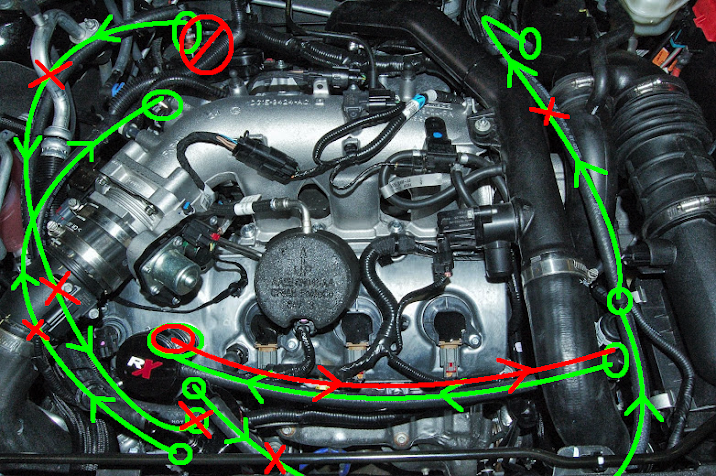
Hopefully this helps: (excuse the shoddy 'Paint' drawing LOL; hope it's not too confusing)
Outlined in
green is the flow of PCV gasses while in non-boost operations.
Outlined in
red is the flow of PCV gasses while under boost.