UPDATES AND CHANGES HAVE BEEN ADDED TO THIS INSTALL / HOW-TO AND ARE LOCATED WITHIN THIS THREAD. DO NOT COMPLETE INSTALL WITHOUT REVIEWING THE CHANGES:
- UPDATED CSS INFO WITH FIRST DRAIN VIDEO - POST #13
- CHANGE IN PROPERLY VENTING CSS - POST #16
- CHANGE IN GENERAL MOUNTING / INSTALLATION - POST #32Alright, it looks like I'm the guinea pig on this one for the XSport (Hence the above changes). Tracy @Tuner Boost did a nice write up on the Flex, and the XSport is almost identical. I just found a couple of places to be a bit confusing, so I thought I would do my own. This is loooong...a little wordy...and with waaay too many pictures...but we're all visual learners.

After install with this particular mounting, the engine cover no longer fits on, it hits on the catch can with this particular mounting of it. Although, if you plan on removing your engine cover (like most of us have already (since who wants to look at a piece of plastic when they open their hood?)), this won't matter. anyway.
If you want more information on what this does, or why you need one (and you do!) see --->
THISSO...let's get started!
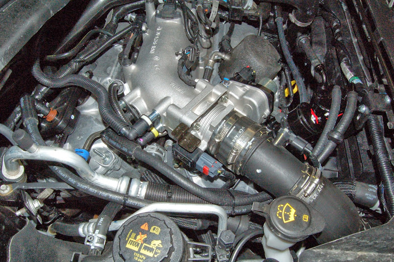
From the front of the engine bay - Pre-Install (front bumper side):

First, remove the PCV line that runs from the passenger's side of the rear valve cover to the vacuum barb on the intake manifold.

Here's a pic of what this line should look like removed. Also, leading into the next step; you will want to roll the foam hose covering back to get to the hard plastic line underneath. To remove these fittings from the barbs, just push the little plastic looking switch on the fitting to the left, this loosens up the fitting and it comes right off.

With this tube removed: carefully slice the hard plastic tube deep enough to split it off of the fitting barbs.
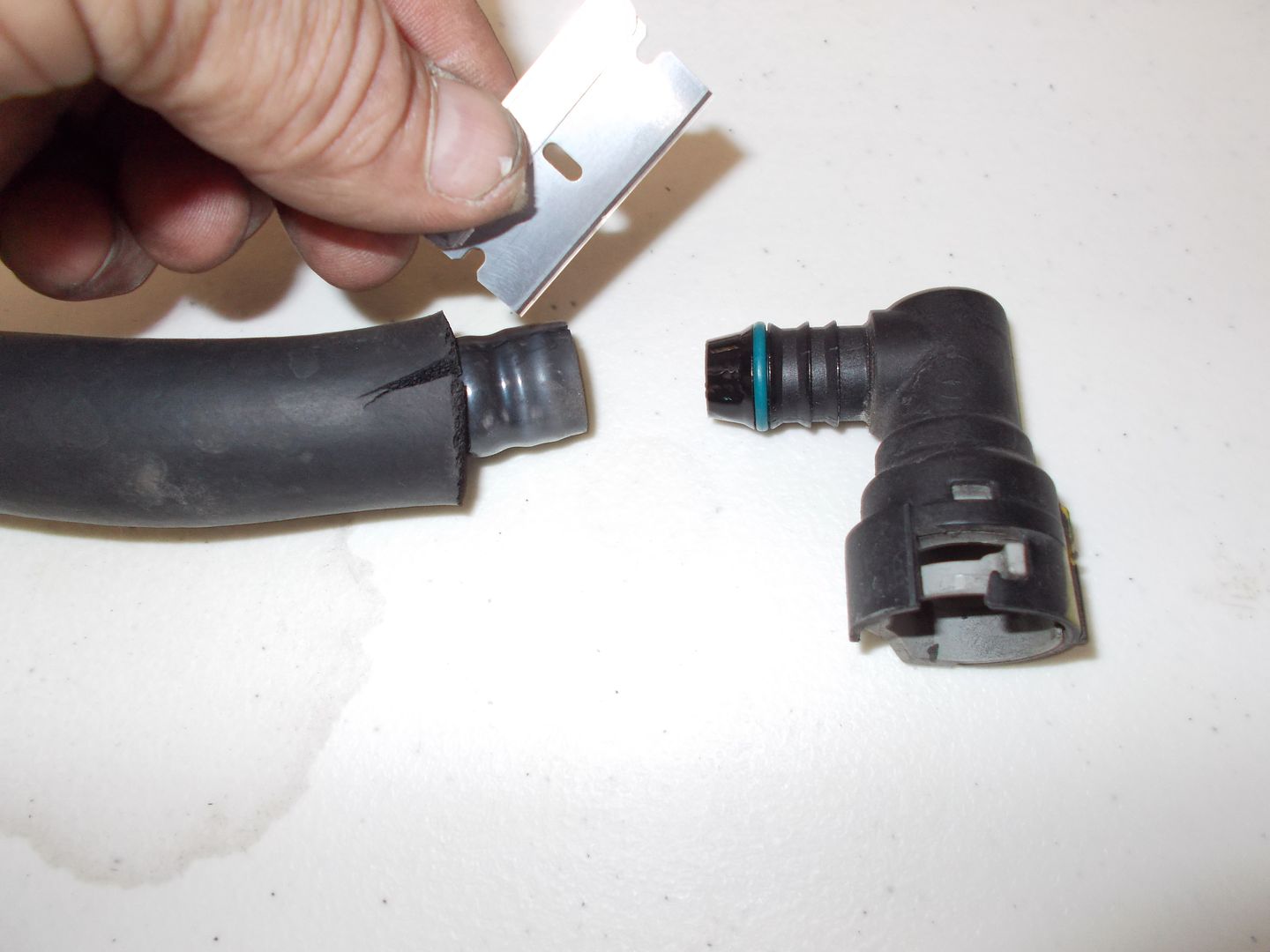
You can now reassemble the fittings.
The kit comes with x3 short lengths of 5/8" hose. Each one of these pieces of hose will end up attached to a 90* fitting on one end, and a barbed reducer on the other end as seen here.
When finished with the first fitting you can reattach it to the PCV fitting on the rear valve cover.

You can then rebuild fitting number 2 and attach it back to the vacuum barb on the intake manifold, where it was removed from.

Original PCV line, now replaced by rebuilt-original fittings

Next, locate the front side PCV line; 3 O'Clock from the oil fill cap.

Remove said fitting

Replace the fitting by placing the rubber cap included with the kit onto the fitting barb.

Follow the front PCV line to the driver's side of the engine, near the air box; remove this fitting.
This fitting will be the third fitting to rebuild with a reducer.

On a side note; at this point I'm sure it's been hard to miss the amount of oil inside the pcv lines as you pull them off. I even had a considerable showing being that I only have 1,600 miles at this point. Granted, I imagine you'll have more blow-by during break-in than is typical in the following miles; but still not what you want to see. Buuuut that's why you get a catch can!

After you rebuild the fitting, re-attach it to the barb.

This is where the front PCV line was, and where you will be attaching a piece of hose after you cut to length.

Next, locate the mounting plate Ford was kind enough to leave wide open for us. It's located on the passenger's side of the engine bay, 6 O'Clock the oil cap, above the radiator, just under the coolant information sticker.

Now you'll need to assemble the can return lines and mounting bracket.
This is how it comes in the box

These are the return lines; this is how them arrived - with the check valves already installed.

They screw onto the fittings on the top of the can, but prior to doing that, I found it better for my application to turn the supply (middle) line 180*. To do this, you have to unscrew one of the bungs, then screw it back into place and attach the return lines.

This is basically the set up I chose for mounting. I found it was best to keep the can as high up as possible so I used the two lower holes on the can.
I ended up with a quick run to the hardware store to get 1/4" x 1" bolt with nut, washers, and a lock washer, to attach the swivel to the bracket. I got a second one for mounting the swivel bracket to the mounting tab on the explorer also.

Side view of the bracket

Catch can and clean side separator installed. The return lines will be reversed for final install.

Cut a section of hose to attach the clean side separator to the drivers side-rebuilt fitting on the intake pipe.

Cut lengths of hose to attach the rear valve cover pcv fitting to the center of the catch can. This is the inlet to the can, so there is no check-valve. One of the can outlets (the ones with the check valves) attaches to the vacuum barb on the intake manifold.
Next is drilling the intake pipes (front and rear). First step here is removing the airbox and loosening the Y-pipe fittings.
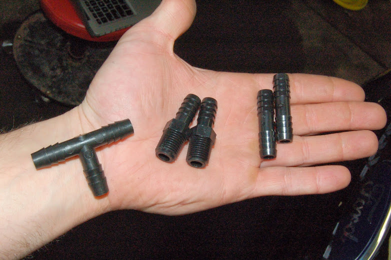
The kit comes with a T-fitting that you will use on the front pipe, and two different types of barb fittings; two butt connectors (right) or two threaded barb fittings (middle).
I chose to use the threaded fittings which requires the pipes to be tapped.
If you want to use the butt connector you can click
HERE to refer to the Flex instructions.
Start by drilling a 1/4" pilot hole in the intake pipe between the small upper vacuum line and the electronic blow off valve return hose. Then broaden the hole by drilling a 27/64" hole and tap it with a 1/4" pipe thread tap.
Since I was drilling a larger hole than what would be necessary for the smaller barb fittings, I wasn't comfortable with the shavings falling down into the intake. So I split the intake at the Y pipe and inserted a flexible shop vac hose to the area I was working in

Repeat the previous steps for the rear intake pipe. For this you will have to find a place after the intake Y where the pipe is easily accessible.

This hole size / tap combo make for a pretty tight fit. I didn't feel the need to use any pipe dope tape or RTV since it's so snug. You only need to go in about half the threads on the fitting. This seats securely, without making too much of an obstruction inside the pipes. The threaded fittings have tapered threads; the deeper you thread them, the tighter they get

I used a small drop of oil on the barbs to slide the hose on, so you're not pushing too hard against the fresh threads on the intake pipes

You'll need to cut another section of hose to go on the front threaded fitting. The shorter you can cut this hose the better, but remember you will have to leave enough room for a barbed fitting to enter the hose from either end. Install the T into the top.

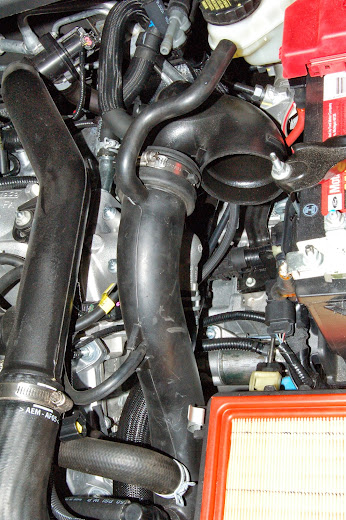
Now you can run your final lengths of hose. I started with the firewall side fitting. After attaching to the fitting, I zip tied it to the intercooler pipe to take the pressure off the fitting from the tight bend. Then ran it in between the two pipes to the T fitting.

A second length of hose then gets installed from the T, around the radiator (front) side of the large intercooler hose, and zip tied it to the electrical bundle that runs along the top of the radiator; back to the second outlet hose (with check valve) on the top of the catch can

Reconnect your intake pipes and replace your air box cover.
Congratulations; You're done! You have successfully installed your new Rx Catch Can and clean side separator. Enjoy your new found intercooler longevity and un-coked intake valves!

THANKS FOR READING!
*edit: INSTALL AT 1,700mi.